In conventional production technologies, designers are forced to adapt their concepts to the constraints imposed by the production process.
To unlock the full potential of 3D-printing, designers need to adapt their approach to avoid parts quickly becoming inefficiently designed or oversized.
Because complexity is often difficult to integrate, classic design tools are not enough to create a new idea. Therefore, new software solutions such as generative design tools are often used.
Which software is needed depends mainly on how you want to use 3D-printing. It may be helpful to list existing capabilities in the design software that you already have access to. It is important to note that some software only makes sense (or is available) for certain processes.
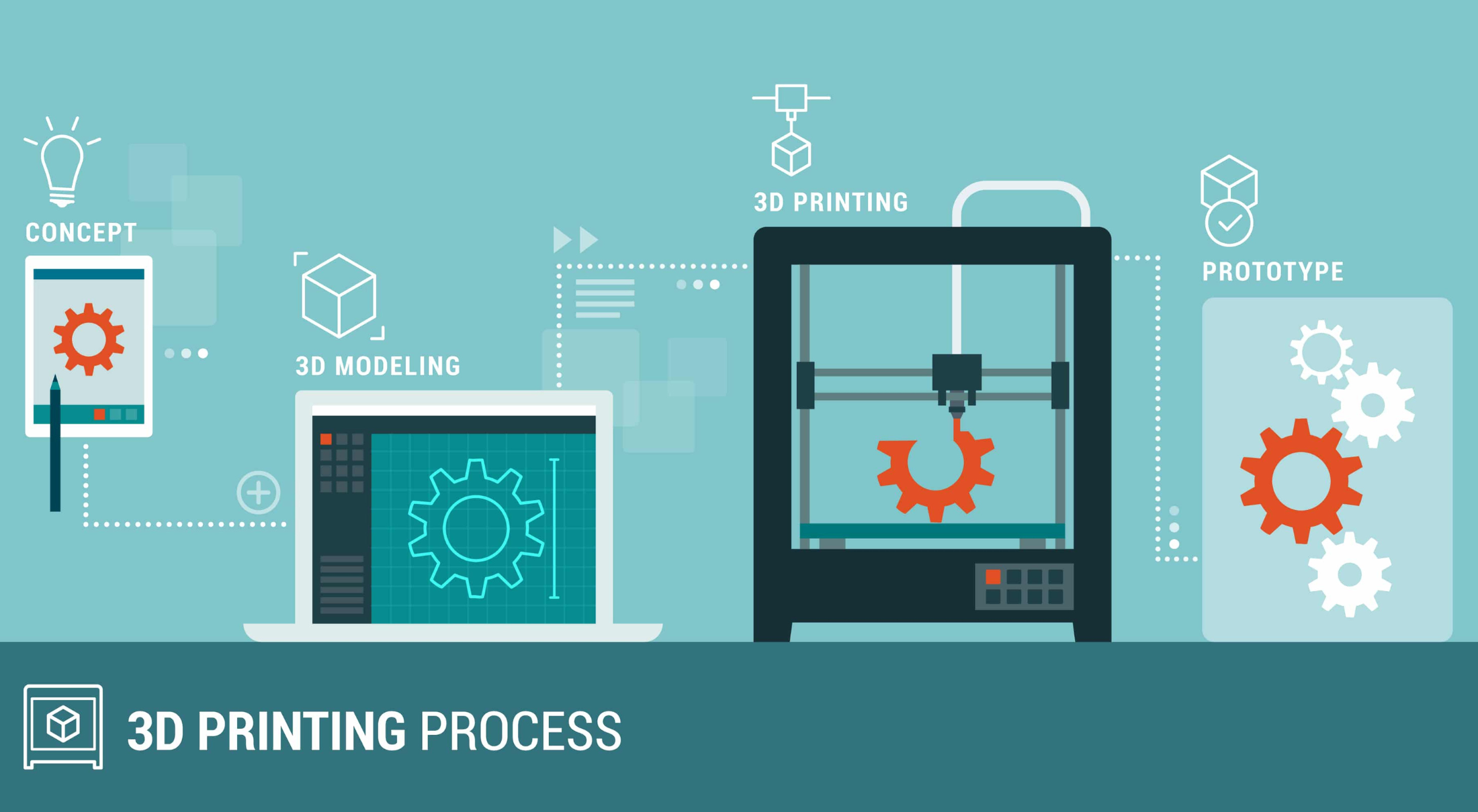
Let’s outline an overview of different types of 3D printing software for every stage of your workflow: designing, repairing, optimizing, and preparing.
Designing – How to Create a Model for 3D Printing

There are two routes to take here. 3D modeling software packages, such as Blender or ZBrush, are excellent tools for virtually designing or sculpting art objects, statues or figurines. If you would like to design your favorite comic book character, this type of software is an excellent choice.
CAD (Computer Aided Design) is aimed at more industrial applications. The basics of CAD start with drawing the design to specific dimensions and converting it into a 3D model. CAD software is a very useful tool for engineering design and is often used where exact dimensions and tolerance are important. Most designs for industrial applications are made in software packages such as Autodesk Inventor or Fusion 360, Dassault Systèmes SolidWorks or Siemens NX.
Repairing – Cleaning up a 3D Scan
This step is only necessary if you are doing reverse engineering, for example when working with 3D scans. Often, only a point cloud is available after scanning. Although these point clouds correspond geometrically and visually accurately to the scanned object, they still need to be converted to a mesh (consisting of edges, points and polygons that define the geometry of an object).
The mesh can be further modified for adapting the design of the part, or to make it more suitable for 3D printing. 3D Systems has an extensive reverse engineering package available with Geomagic Design X to create editable solid models that are compatible with your existing CAD software. Materialize 3-magic also offers that possibility. The result is a ‘waterproof’ model optimized for 3D printing.
Optimizing – Design Optimization for Industrial Applications

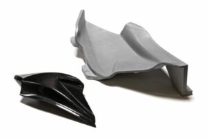
New simulation processes such as generative design make an important contribution to Additive Manufacturing. Generative design follows the evolutionary approach of nature, where we see a wide range of solutions for critical support structures that pose an integral part of the design. The freedom of form of 3D printing allows us to imitate these structures.
By entering specific criteria for a part, such as specific mounting points, the software adjusts the topology of a design to automatically meet the requirements. Advanced algorithms generate the ideal shape based on parameters such as design space, material properties and loading forces. This makes it possible to evolve to an optimized, weight-efficient shape within minutes.
The German Altair offers a user-friendly solution with SolidThinking Inspire, and MSC Software also has a solution available with Nastran SOL 200. In addition, to simulate the performance of the parts to be printed, mechanical FEA solvers are often integrated into most topology optimization and lattice generation software. There are also stand-alone solutions for structural calculations such as Siemens Simcenter 3D, MSC Nastran or MSC Marc.
Parts should be re-analyzed after topology optimization to ensure that the design changes have not shifted the part’s performance beyond the required specifications. In addition to topology optimization, analysis plays an important role in simulating performance – including the performance between traditionally manufactured and 3D-printed parts to be able to compare.
Preparing – The Final Step in Print Preparation
This step is necessary if you plan to print yourself (as opposed to outsourcing production). When you have a CAD file, you need to make sure you get the best possible print result with the printer you have available. “Slicing” your 3D model means taking your design and slicing it into individual layers. The software then generates the tool path (.gcode) the printer will use for printing.
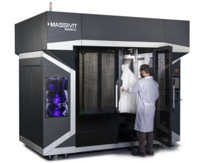
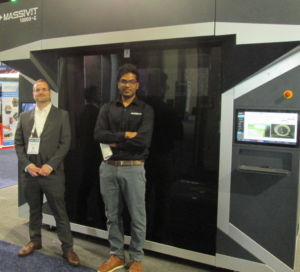
With Gel Dispensing Printing technology (GDP) technology, the Massivit Smart slicing software serves as a translator between a virtual 3D model and the Massivit printers. This software package allows you to import .stl and .obj files, fix errors, modify designs, and prepare the build platform. The print preparation software also automatically suggests placing support ribs (to stabilize the print during the process) at the best possible location, and the ideal location and positioning of the part on the build table.
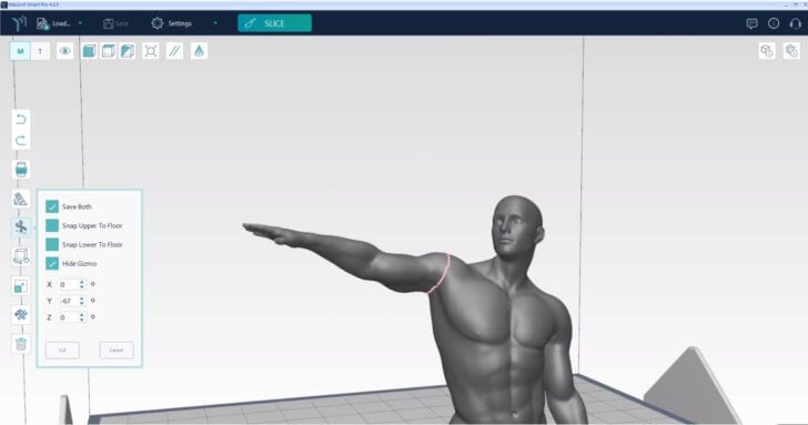
Massivit Smart even has a ‘Quick Estimation Mode’ available after loading the file, which gives a rough material and print time estimation without the need of fully slicing the part first. It even works on parts that are bigger than the printer!
The actual printing process can also be simulated with the ‘Toolpath Analyzer’ and ‘Toolpath Preview’ functions. These functions allow for a better selection of process parameters, or for assessing how changes in parameters influence the behavior of parts. The software can be used to investigate the influence of material selection, the implantation on the build plate, and the necessity of infill ribs and support structures.
The software even predicts the possible deformation or areas of the part that might be problematic to print, automatically suggesting design solutions to reduce them. This way, Massivit Smart guides the production engineer in adapting a part to achieve “first time right” printing.
These kinds of software solutions, which allow closer integration between design and production, are increasingly in demand and will become even more important in the future.